Featured Post

Induction Motor Interview Questions with Answers | Part-1

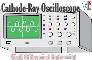
Cathode Ray Oscilloscope ( C. R. O. ) | Working and Application of C. R. O

Cathode Ray Oscilloscope ( C. R. O. ) | Working and Application of C. R. O


CRO
Cathode Ray Oscilloscope ( C. R. O. ) | Working and Application of C. R. O


Definition and Basic Details of C. R. O.


A cathode-ray oscilloscope is an instrument which presents signal wave-forms visually.


It is also useful for comparing two signals in phase,frequency or amplitude.


A  C.R.O.can operate upto 50 MHz, can allow viewing of signals within a time span of a few
nanoseconds and can provide a number of waveform displays simultaneously on the screen.


It also has the ability to hold the displays for a short or long time (of many hours)so that original signal may be compared with one coming on later.


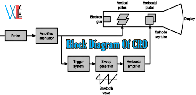
A block diagram of cathode-ray oscilloscope is shown in below figure


Block Diagram of CRO
Block Diagram of cathode Ray Oscilloscope


Cathode Ray Tube(C.R.T.)


A cathode ray tube is the 'heart of an oscilloscope and is very similar to the picture tube in a television set.


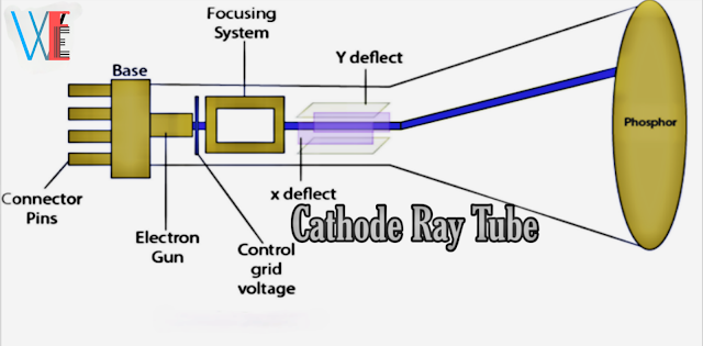
Cathode Ray Tube
Cross sectional view of Cathode Ray Tube


Figure shows the cross-sectional view of
a general-purpose electrostatic C.R.T.


It has the following four major components:


1.An eloctron gun

Electron gun produces a stream of electrons.


2.Focusing and accelerating anodes

They produce a narrow and sharply-focused
beam of electrons.


3.Horizontal and vertical deflecting plates

Horizontal and vertical deflecting plates are use for the path of beam.


4.An evacuated glass envelope with a
phoephorescent screen

It will be produces a bright spot when struck by a high velocity electron beam.


Working of a C.R.O.


When a signal is to be displayed or viewed on the screen it is applied across the Y-plates of a
cathode ray tube.


But to see its waveform or pattern, it is essential to spread it out horizontally from
left to right.


This is achieved by, applying a sawtooth voltage wave to X-plates.


Under these conditions, the electron beam would move uniformly from left to right thereby graphing vertical variations of the input signal versus time.Due to repetitive tracing of the viewed waveform, we get a continuous display because of persistence of vision.

However, to get a stable stationary display on
vertical the screen, it is essential to synchronize the horizontal sweeping of the beam with the input signal across Y-plates.


The signal will be properly synced
only when its frequency equals the sweep-generator frequency.


The usual method of synchronizing the
input signal is to use a portion of the input signal to trigger the sweep generator so that the frequency of the sweep signal is locked or synchronised to the input signal.


It is called internal aync because the synchronization is obtained by internal wiring connections.

Applications of C.R.O.


✓Tracing of an actual waveform of current or voltage.


✓Determination of amplitude of a variable quantity.


✓Comparison of phase and frequeney.


✓In televisions.


✓In radar.


✓For finding B.H.curves for hysteresis loop.


✓For engine pressure analysis.


✓For studying the heart beata, nervous reactions etc.


✓For tracing transistor curves.


May You like to read article related to this article 👇👇👇


Comments

Post a Comment

Popular posts from this blog

Introduction to Arduino | Pin Function of Arduino | Working Process of Arduino

Introduction to Arduino | Pin Function of Arduino | Working Process of Arduino Introduction to Arduino | Pin Function of Arduino | Working Process of Arduino Introduction To Arduino Arduino is an Italian company that designs and manufactures Open Source Hardware (Microcontroller) and Open Source software or IDE (Integrated Development Environment). Arduino hardware is such a programmable computerized platform, by working on which the user can combine the hardware and software and prepare the electronic brain according to his own and can control the electronic devices from that electronic brain. What is arduino? If you want to understand more easily, then we can say that Arduino microcontroller is an empty brain, in which you can upload memory by coding or programming through arduino software, so these are called open source. Arduino works like a CPU of a board computer. Right now the microcontroller of the arduino of this time that we can take up is lik

What is Microprocessor? | Block Diagram of Microprocessor | Application of Microprocessor

What is Microprocessor? | Block Diagram of Microprocessor | Application of Microprocessor What is Microprocessor? | Block Diagram of Microprocessor | Application of Microprocessor Basic Detail Of Microprocessor The  microprocessor is a semiconductor device consisting of electronic logic circuits manufactured by using either a large scale(LSI) or very large scale integration(VLSI) technique. The microprocessor is capable of performing computing functions and making decisions to change the sequence of program execution. In large computers, the central processing unit(CPU) performs these computing functions and it is implemented on one or more circuit boards. The microprocessor is in many ways similar to the CPU, however, the microprocessor includes all the logic circuitry(including the control unit)on one chip. The microprocessor consists of the following three segments which is shown in below diagram. Block Diagram of Microproce

What is Instrumentation? And Modes of Measurement

What is Instrumentation? And Modes of Measurement Definition of Instrumentation The technology of using instruments to measure and control the physical and chemical properties of materials is called “ instrumentation ". What is Instrumentation? And Modes of Measurement When the instruments are used for the measurement and control of industrial manufacturing , conversion or treatment processes, the term process instrumentation is applied. When the measuring and controlling instruments are combined so that measurements provide impulses for remote automatic action, the result is called a control system. Modes of Measurement There are the three modes of measurement: 1. Primary Measurement 2. Secondary Measurement 3. Tertiary Measurement All the three modes are described below: (1) Primary Measurements In the primary measurement sought value of a parameter is determined by comparing it directly with reference standar