Featured Post

Induction Motor Interview Questions with Answers | Part-1

Percentage Differential Relay and Protection for Power Transformer

Percentage Differential Relay and Protection for Power Transformer


The differential protection scheme is used for the protection of transformers having rating 5 MVA and above against internal phase to phase and phase to earth faults.


Differential relay
Percentage Differential Relay and Protection for Power Transformer


The basic principle of operation of differential relay is that the vector difference of two or more similar electrical quantities current or voltage goes beyond the specified or the set
value then the relay will operate otherwise the relay will not operate.


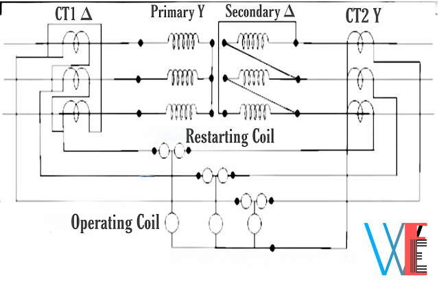
The connection diagram of this type of protection is shown in below figure:


Percentage Differential protection for power transformer
Circuit Diagram of Percentage Differential Relay and Protection for Power Transformer


The primary winding of transformer is connected in star and the CTs on that side are connected in delta.


The secondary winding of transformer is connected in delta and the CTs on that side are connected in star.


This prevents the out of balance current flowing through the relay coil due to the phase displacement between the primary and secondary in the healthy condition.


The restraining coil is connected in the pilot wires.


The operating coils are connected between the mid points of the restraining coil and the neutral pilot wire.


Current increases to high value when the transformer feeds the fault outside its
protection zone.


The differential current flows if the characteristics of the CTs are not identical.


But in this case the restraining current also increases so the relay cannot operate.


But when there is internal fault in transformer, the differential current increases and the relay operates.


The differential protection of transformer is also known as Merz-Price protection for the transformer.


Comments

Popular posts from this blog

Introduction to Arduino | Pin Function of Arduino | Working Process of Arduino

Introduction to Arduino | Pin Function of Arduino | Working Process of Arduino Introduction to Arduino | Pin Function of Arduino | Working Process of Arduino Introduction To Arduino Arduino is an Italian company that designs and manufactures Open Source Hardware (Microcontroller) and Open Source software or IDE (Integrated Development Environment). Arduino hardware is such a programmable computerized platform, by working on which the user can combine the hardware and software and prepare the electronic brain according to his own and can control the electronic devices from that electronic brain. What is arduino? If you want to understand more easily, then we can say that Arduino microcontroller is an empty brain, in which you can upload memory by coding or programming through arduino software, so these are called open source. Arduino works like a CPU of a board computer. Right now the microcontroller of the arduino of this time that we can take up is lik

Variable Inductance Transducer | Classification Of Variable Inductance Transducer

Variable Inductance Transducer | Classification Of Variable Inductance Transducer Variable Inductance Transducer | Classification Of Variable Inductance Transducer These are based on a change in the magnetic characteristic of an electrical circuit in response to a measurand which may be displacement, velocity, acceleration etc. Variable inductive transducer may be classified as follows: 1.Self-generating type In this type voltage is generated because of the relative motion between a conductor and a magnetic field. These may be further classified as follows: (A)Electromagnetic type (B)Electrodynamic type (C)Eddy current type 2.Passive type In this type the motion of an object results in change in the inductance of the coils of the transducer. These may be further classified as follows: (A)Variable reluctance (B)Mutual inductance (C)Differential transfer type 1.Self-generating Type (A)Eleotromagnetic t

Induction Motor Interview Questions with Answers | Part-1

Induction Motor Interview Questions with Answers | Part-1 Induction Motor Interview Questions with Answers | Part-1 Q.1 The frame of an induction motor is made of (A) aluminium (B) silicon steel (C) closed grained cast iron (D) stainless steel (E) bronze Answer:  (C) closed grained cast iron Q.2 The stator frame is an induction motor is used to (A) hold the armature stampings in position (B) ventilate the armature (C) protect the whole machine (D) provide return path for flux Answer:  (A) hold the armature stampings in position Q.3 The stator core of a 3 phase induction motor is laminate in order to reduce the (A) eddy current loss (B) hysteresis loss (C) both hysteresis and eddy current loss (D) weight of the stator (E) windage and friction losses Answer: (A) eddy current loss Q.4 An induction motor works with (A) dc only (B) ac only (C) ac and dc both (D) none of these Answer:  (B) ac only Q.5 Which of the following statement associated with polyphase induction motor is/are correct?