Variable Inductance Transducer | Classification Of Variable Inductance Transducer
These are based on a change in the magnetic characteristic of an electrical circuit in response to a measurand which may be displacement, velocity, acceleration etc.
Variable inductive transducer may be classified as follows:
1.Self-generating type
In this type voltage is generated because of the relative motion between a conductor and a magnetic field.
These may be further classified as follows:
(A)Electromagnetic type
(B)Electrodynamic type
(C)Eddy current type
2.Passive type
In this type the motion of an object results in change in the inductance of the coils of the transducer.
These may be further classified as follows:
(A)Variable reluctance
(B)Mutual inductance
(C)Differential transfer type
1.Self-generating Type
(A)Eleotromagnetic type
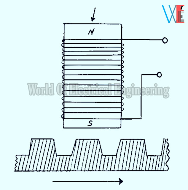
Figure 1 shows an electromagnetic type of self-generating variable inductance transducer.
It consists of a permanent magnet core on which a coil is directly wound.
When a plate of iron or other ferromagnetic material is moved with respect to the magnet, the flux field expands or collapses and a voltage is induced in the coil.
This device is used for indication of angular speed. The measurements of speed can be
made with great accuracy when the pickup is placed near the teeth of a rotating gear.
(B) Electrodynamic type
This type of transducer(linear and rotational) is shown in Below figure 2.
In this type coil moves within the field of the magnet.The turns of the coil are perpendicular to the intersecting lines of force.
When the coil moves it induces a voltage which at any moment is proportional to the velocity of the coil.
The principle of these transducers is used in the magnetic flow meters.
(C) Eddy Current type
Figure 3 shows an eddy current type self-generating variable inductance transducer.
2.Passive Type
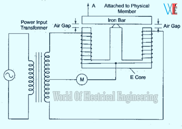
(A) Variable reluctance transducer
In these transducer a change in the reluctance of the magnetic circuit by a mechanical input results in a similar change both in the inductance and inductive reactance of the coils.
The change in inductance is then measured by suitable circuitry and related to tho value of the mechanjical input.
The magnetic circuit reactance may be changed by affecting a change:
(1) In the air gap or
(2) In the amountltype of core material.
Transducers which make use of air gap change are referred as reluctance type.
Transducers which utilize a variable core are referred as permeance type.
Here the inductance of a single coil is changed through the variable air gap.
The change in inductance may be calibrated in terms of movement of the armature.
This principle of variable reluctance is used for the measurement of dynamic quantities such
as:
✓ Pressure
✓ Force
✓ Displacement
✓ Acceleration
✓ Angular position etc.
Fig. shows a variable permeance the inductance of coil is changed by varying the core material.
The transducer consists of a coil of many turns of wire wound on a tube of insulating material with a moveable core of magnetic material.
When the coil is energized and the core enters
solenoid cell, the inductance of the coil increases in proportion to the amount of metal within the coil.
It is primarily used for the measurement of:
(1)Displacement
(2)Strain
(3)Force
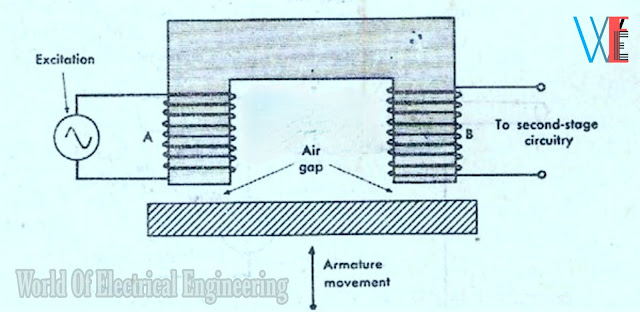
(B) Mutual inductance transducer
A two-coil mutual inductance transducer is
shown in Fig.
It consists of an energising circuit coil X and a pickup coil Y. A change in the position of
the armature by a mechanical input changes the airgap.
This causes a change in the output from coil Y,
which may be used as a measure of the displacement of the armature, such that the mechanical input.
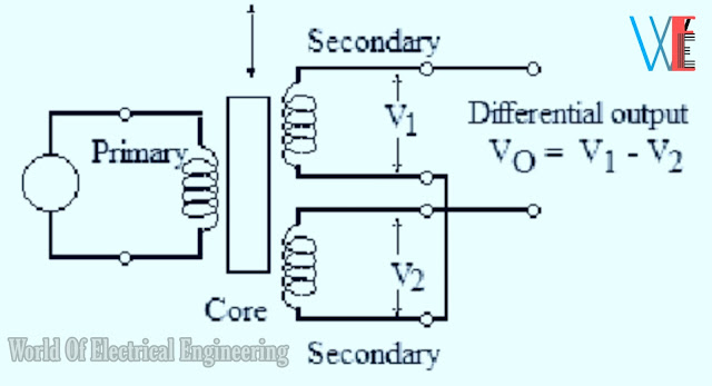
(C) Linear Variable Differential Transformer (LVDT)
LVDT is a passive inductive transducer and
is commonly employed to measure force or weight, pressure and acceleration etc. which depend on force in terms of the amount and direction of displacement of an object.
Construction of LVDT
It consists of one primary winding P and two secondary windings S1 and S2.
which are placed on either side of the primary mounted on the same magnetic core.
The magnetic core is free to move axially
inside the coil assembly and the motion being measured is mechanically coupled to it.
The two secondaries S1 and S2 have equal number of turns but are connected in series
opposition so that e.m.f E1 and E2 induced in them are 180° out of phase with each other and, hence,cancel each other out,[See Fig.]
The primary is energised from a suitable A.C.source.
Working
When the core is in the centre called reference position, the induced voltages E1 and E2 are equal and opposite.
Hence they cancel out and the output voltage Vo is zero.
When the external applied force moves the core towards coil S2, E2 is increased but E1 is
decreased in magnitude though they are still antiphase with each other.
The net voltage available is ( E2 - E1 ) and is in phase with E2.
Similarly, when the magnetic core moves towards coil S1, E1 > E2 and Vo = E1 - E2 and is in phase with E1.
Thus, from above discussion, we find that the magnitude of Vo is a function of the distance
mnoued by the core and its polarity or phase indicates as to in which direction it has moved.
If core is attached to a moving object, the magnitude of Vo gives the position of that object.


Mementos don't necessarily have to be functional items that people use every day, though it is possible for them to double as mementos. One example of this is a watch that was given out at a corporate luncheon. This item could be worn every day or put up on a shelf among other precious objects. Another memento might be a clock tower made from sterling silver which would sit on someone's desk holding a pen and paper in place.
ReplyDeletepromotional gifts