Over Current Protection Of Transformer
 |
| Over Current Protection Of Transformer |
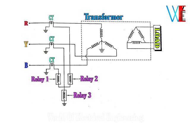
Now we learn over current protection using circuit Diagram which is shown in below figure.
 |
Circuit Diagram of Over Current Protection Of Transformer |
Transformer is connected in star-delta.CTs are connected in the primary lines.
Over current Relay-1 and 2 is connected in two phases.
Relay-3 is connected across the star point of the over current relay and the earth.
Over current Relay-1 and 2 operates when there is phase to phase fault or when there is
over load.
Relay-3 operates in case of the earth fault.
Similar protection can be given in the secondary winding also.
This type of protection is used for primary protection of small transformers and back-up
protection of large transformers.
The primary winding of transformer is connected in star and the CTs on that side are
connected in delta.
The secondary winding of transformer is connected in delta and the CTs on that side are connected in star.
The prevents the out or balance current flowing through the relay coil due to the phase displacement between the primary and secondary in the healthy condition.
The restraining coil is connected in the pilot wires.
The operating coils are connected between
the mid points of the restraining coil and the neutral pilot wire.
current increases to high value when the transformer feeds the fault outside its protection zone.
The differential current flows if the characteristics of the CTs are not identical.
But in this case the restraining current also increases so the relay cannot operate.
But when there is internal fault in transformer, the differential current increases and the relay operates.
The differential protection of transformer is also known as Merz-Price protection for the
transformer.

Comments
Post a Comment