Featured Post

Induction Motor Interview Questions with Answers | Part-1

Switching Voltage Regulators | Classification of SMPS

Switching Voltage Regulators | Classification of SMPS


The dc output of the rectifier or battery is not regulated. It varies according to the load variations.

Voltage Regulators
Switching Voltage Regulators | Classification of SMPS


Switching mode regulators are used to convert unregulated dc to regulated DC output.


The switching mode regulators use dc choppers.


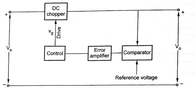
Below figure shows the block diagram of switching mode regulator. The dc chopper takes the input Vs from some unregulated supply. 
Voltage Regulators
Block Diagram of Switching Mode Regulator 


The chopper may use Transistor, MOSFET, IGBT, SCR or GTO for switching.


The comparator compares the reference voltage with output voltage. The reference voltage is set for the particular output voltage. 


The comparator generates the error signal. This error signal acts as the control voltage.


The control block uses the control voltage Vc, to generate the drives of the chopper.


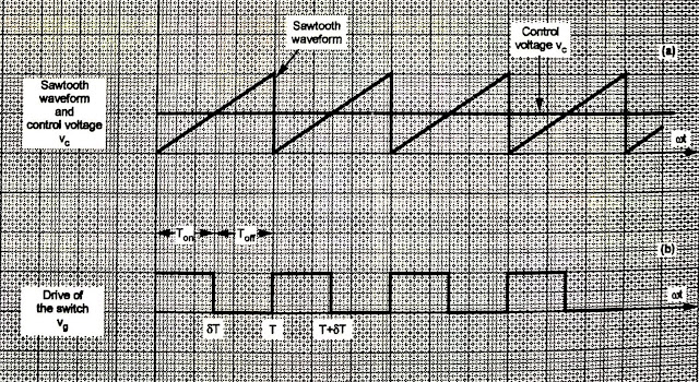
Below figure shows the control waveforms. The control voltage Vc is compared with the sawtooth waveform.
Voltage Regulators
Waveforms of Switching voltage Regulators


The result of comparison is the drive of the chopper as shown in second waveform. This drive is given to the switch in the chopper.


The sawtooth waveform is generated by an oscillator in the control circuit.


The frequency of the sawtooth waveform decides the switching frequency of the chopper.


Normally the switching period is 100 times longer than the switching time of the switch.


Excessive switching frequencies may increase losses in the chopper.


The filters are normally used in the output to make the output voltage ripple free and smooth. 


The regulation is also improved.The width of the drive is continuously adjusted to regulate output voltage.


Hence it is also called as Pulse Width Modulation (PWM)control.


Classification of SMPS


Classification of SMPS is mentioned below:

1. SMPS


       (A) Isolated Converters
       (B) Non isolated Converters


(A) Isolated Converters


       ✓ Unidirectional Core Excitation

           1. Flyback Converter
           2. Forward Converter


       ✓ Bidirectional Core Excitation

           1. Push-Pull Converter
           2. Half Bridge Converter
           3. Full Bridge Converter


(B) Non isolated Converter


           1. Buck Regulator
           2. Boost Regulator 
           3. Buck Boost Regulator
           3. Cuk Regulator


May You like to Read this Article 👇👇


Comments

Popular posts from this blog

Introduction to Arduino | Pin Function of Arduino | Working Process of Arduino

Introduction to Arduino | Pin Function of Arduino | Working Process of Arduino Introduction to Arduino | Pin Function of Arduino | Working Process of Arduino Introduction To Arduino Arduino is an Italian company that designs and manufactures Open Source Hardware (Microcontroller) and Open Source software or IDE (Integrated Development Environment). Arduino hardware is such a programmable computerized platform, by working on which the user can combine the hardware and software and prepare the electronic brain according to his own and can control the electronic devices from that electronic brain. What is arduino? If you want to understand more easily, then we can say that Arduino microcontroller is an empty brain, in which you can upload memory by coding or programming through arduino software, so these are called open source. Arduino works like a CPU of a board computer. Right now the microcontroller of the arduino of this time that we can take up is lik

What is Microprocessor? | Block Diagram of Microprocessor | Application of Microprocessor

What is Microprocessor? | Block Diagram of Microprocessor | Application of Microprocessor What is Microprocessor? | Block Diagram of Microprocessor | Application of Microprocessor Basic Detail Of Microprocessor The  microprocessor is a semiconductor device consisting of electronic logic circuits manufactured by using either a large scale(LSI) or very large scale integration(VLSI) technique. The microprocessor is capable of performing computing functions and making decisions to change the sequence of program execution. In large computers, the central processing unit(CPU) performs these computing functions and it is implemented on one or more circuit boards. The microprocessor is in many ways similar to the CPU, however, the microprocessor includes all the logic circuitry(including the control unit)on one chip. The microprocessor consists of the following three segments which is shown in below diagram. Block Diagram of Microproce

What is Instrumentation? And Modes of Measurement

What is Instrumentation? And Modes of Measurement Definition of Instrumentation The technology of using instruments to measure and control the physical and chemical properties of materials is called “ instrumentation ". What is Instrumentation? And Modes of Measurement When the instruments are used for the measurement and control of industrial manufacturing , conversion or treatment processes, the term process instrumentation is applied. When the measuring and controlling instruments are combined so that measurements provide impulses for remote automatic action, the result is called a control system. Modes of Measurement There are the three modes of measurement: 1. Primary Measurement 2. Secondary Measurement 3. Tertiary Measurement All the three modes are described below: (1) Primary Measurements In the primary measurement sought value of a parameter is determined by comparing it directly with reference standar