Featured Post

Induction Motor Interview Questions with Answers | Part-1

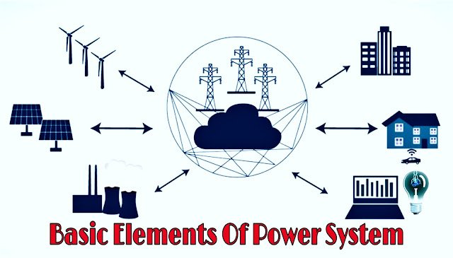
Basic Elements of Power System | Electrical Power System Theory

Basic Elements of Power System | Electrical Power System Theory


Power system can be divided in to
three different parts :

(1) Generating station

(2) Load centre

(3) Link joining 1 and 2


Electrical Power System
Basic Elements of Power System | Electrical Power System Theory


Electric power is generated in generating station T1 includes the generator, prime mover and necessary equipments to run the prime mover, exciter, step up transformer, circuit breaker etc.


Load centre includes consumers which consume electric power such as factory, shops, water supply, hospitals, cinemas, domestic consumers etc.


Generating station and the load centre are connected through the transmission line, substation and distribution lines.


Modern power supply system is not as simple as described above. Especially the link joining the generating station and the load centre is complicated.


Single line diagram of power supply system is shown in below diagram:


Electrical Power System
Single Line Diagram Of Electrical Power Supply System


Power is generated at voltage of around 11 kV. This voltage is stepped up to the voltage of transmission with the help of step up transformer.


Normally the voltage of transmission is 220 kV or 400 kV. Long distance transmission lines are run in different areas.


This is called high voltage transmission or primary transmission.There is receiving station at the end of each line.


In this,the voltage is normally stepped down From substation 66 kV lines are run in to different areas.This is called secondary
transmission.


Substation is kept at the end of each 66 kV line.
In substation 66 kV voltage is stepped down to 11 kV with the help of step down transformer.


High voltage consumers like factories, big industries are given supply using 11 kV feeders. This is called high voltage distribution or primary distribution.


Some 11 kV feeders are taken in to different areas.There is distribution transformer at
the end of each 11 kV feeder.


This transformer is installed on the pole.This transformer has voltage ratio of 11 kV/415 V.
Different 415 V distribution lines are run in different streets.


From these lines the L.T. domestic consumers are given either 3-phase supply or 1 phase supply. This is called low voltage or secondary distribution.


In addition the modern supply system is interconnected, so that if trouble arises in one
substation, the power can be fed from other substation.


Complications increase due to the interconnection but considering other advantages of interconnection, the complication has to be accepted to 66 kV.


May You like to Read this Article 👇👇

Comments

Popular posts from this blog

Introduction to Arduino | Pin Function of Arduino | Working Process of Arduino

Introduction to Arduino | Pin Function of Arduino | Working Process of Arduino Introduction to Arduino | Pin Function of Arduino | Working Process of Arduino Introduction To Arduino Arduino is an Italian company that designs and manufactures Open Source Hardware (Microcontroller) and Open Source software or IDE (Integrated Development Environment). Arduino hardware is such a programmable computerized platform, by working on which the user can combine the hardware and software and prepare the electronic brain according to his own and can control the electronic devices from that electronic brain. What is arduino? If you want to understand more easily, then we can say that Arduino microcontroller is an empty brain, in which you can upload memory by coding or programming through arduino software, so these are called open source. Arduino works like a CPU of a board computer. Right now the microcontroller of the arduino of this time that we can take up is lik

What is Microprocessor? | Block Diagram of Microprocessor | Application of Microprocessor

What is Microprocessor? | Block Diagram of Microprocessor | Application of Microprocessor What is Microprocessor? | Block Diagram of Microprocessor | Application of Microprocessor Basic Detail Of Microprocessor The  microprocessor is a semiconductor device consisting of electronic logic circuits manufactured by using either a large scale(LSI) or very large scale integration(VLSI) technique. The microprocessor is capable of performing computing functions and making decisions to change the sequence of program execution. In large computers, the central processing unit(CPU) performs these computing functions and it is implemented on one or more circuit boards. The microprocessor is in many ways similar to the CPU, however, the microprocessor includes all the logic circuitry(including the control unit)on one chip. The microprocessor consists of the following three segments which is shown in below diagram. Block Diagram of Microproce

What is Instrumentation? And Modes of Measurement

What is Instrumentation? And Modes of Measurement Definition of Instrumentation The technology of using instruments to measure and control the physical and chemical properties of materials is called “ instrumentation ". What is Instrumentation? And Modes of Measurement When the instruments are used for the measurement and control of industrial manufacturing , conversion or treatment processes, the term process instrumentation is applied. When the measuring and controlling instruments are combined so that measurements provide impulses for remote automatic action, the result is called a control system. Modes of Measurement There are the three modes of measurement: 1. Primary Measurement 2. Secondary Measurement 3. Tertiary Measurement All the three modes are described below: (1) Primary Measurements In the primary measurement sought value of a parameter is determined by comparing it directly with reference standar